Thursday, August 17, 2006

Tiny Astronaut figure - Step 8 (Photography)

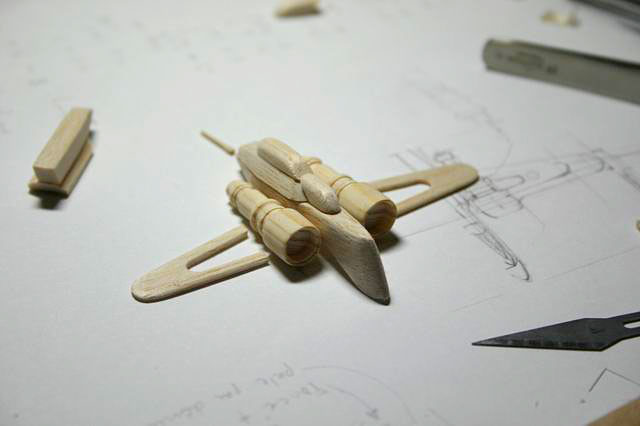
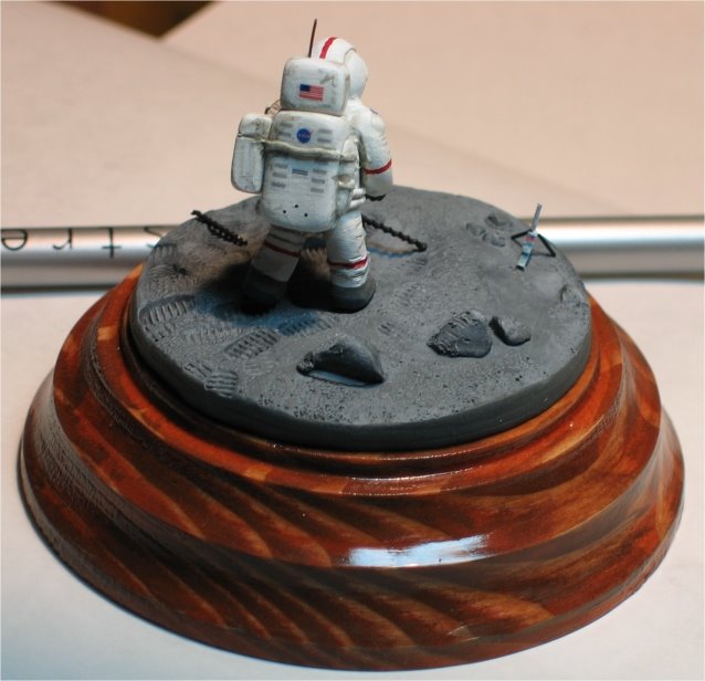
I got some emails requests on how to photograph such a tiny models.

I could say the technique is all in the lights, but the camera settings has a lot to do with the results also.

I got some ideas from the following sites.
Light box / light tent
Photographing miniatures
Indoor photography
DIY lightbox

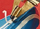
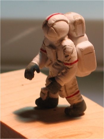
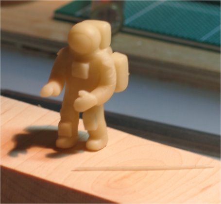
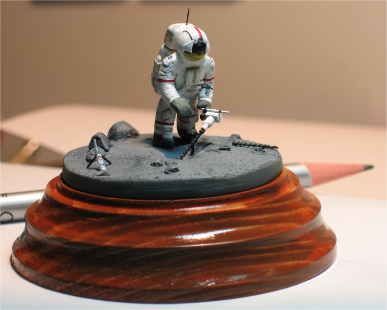
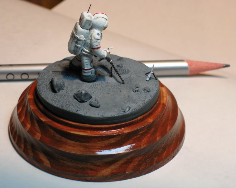
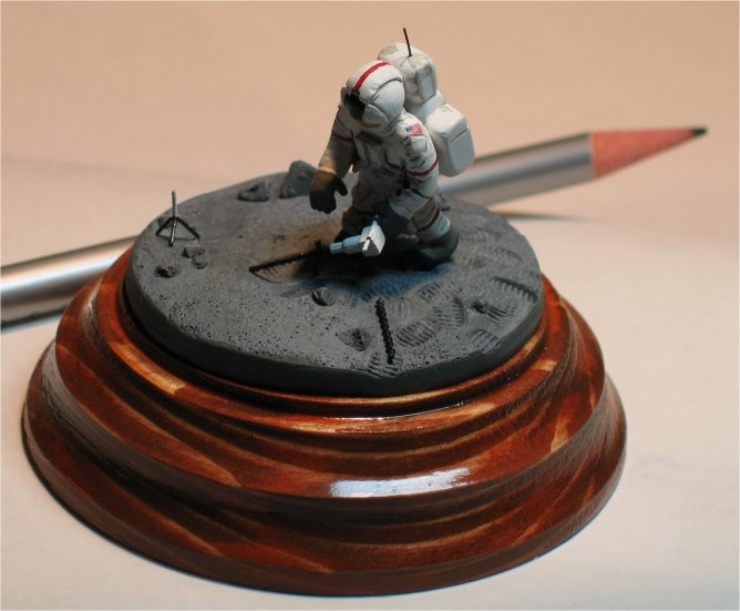
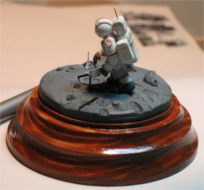
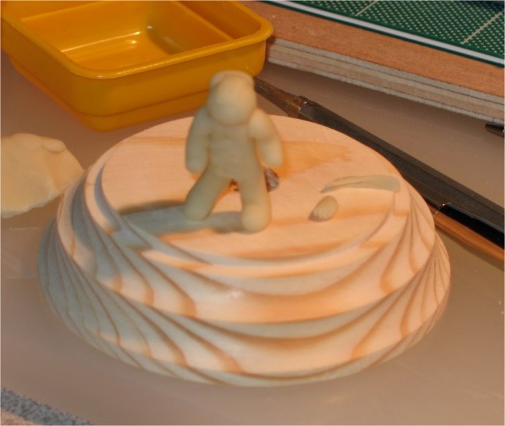
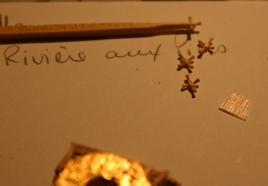
Basically I've chosen a “no flash” setting with the macro option enable on my Canon A95, the macro setting is usually represented by a tulip logo.
Without the direct reflection of lights, with the help of the paper rolls over the neon’s, you have a crisper image quality. But you must use a steady hand or a tripod for such a low light setting.

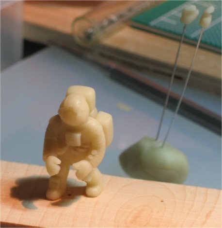
So basically it is done with the following points only.
- Paper light filtering (just 2 sheets of paper rolled)
- No flash
- Macro setting
- No hands shaking allowed.

Monday, August 07, 2006

Tiny Astronaut figure - Step 7 (A little plus value)

For a fussier look to the base, or a more professional look to it, chose your preference. You can acquire some rolls of adhesive backed felt. It comes in a variety of colors. For this base I've chosen a more conservative green look.


Here's the underside of the base, once the felt is stick to it.


Final look.


I acquire my rolls of felt at Lee Valey

Go to Final pictures or back to Step 6

Sunday, August 06, 2006

Arc-170 construction process - Step4 (Final)

For the decals step, I've studied each logo, each lines and each graphics to later reproduce them in Paint shop pro, after they were printed on a sheet of decal paper.


The radiators inside the ailerons were printed on 2 surfaces with thinker paper, almost cardboard but acid free. This gave me a thin piece with a lot of details. (little grey wing part on right of the picture).


For the ailerons installation, I had to use a small jig to hold them in place. It was important to have a perfect angle between the 4. For the ones on the underside of the wings I used the same technique but only holding the model upside down, it was done by holding it from its vertical pole, because putting the first 2 little ailerons made the model very fragile.

The dirt was painted by using the dry brush technique. Paint is wiped from the Brush with a towel before applying it to the model.


Final results, with a closer look.


Like said earlier, if you have any specific questions about this construction or for any other matter, don’t hesitate to send a comment from the link below.

Here's a link with other pictures taken during the construction process. ARC-170

Back to Step 3

Saturday, August 05, 2006

Arc-170 construction process - Step3

Balsa wood is a very smooth and porous material, curse by some purist (mostly museum quality scale model builder) venerated by other, including myself, It is a very workable product and is very easy to acquire. Unfortunately its grains and pores are always showing after painting, thus divulging the scale of the work. A lot of people had found solutions to hide the grain of the wood, one of them is to apply several layer of CA glue followed with sanding between each layer, I had found this technique to much laborious and smelly. Fortunately for me, I came across this product, Micro-fill for balsa, it is water base and you just have to sand a little after its application, if your patient enough it will hide 100% of the porosity on the wood. For my model discuss here, I applied it only on 55% of the surface, even if this product does miracle for hiding the wood grain I don't particularly love the sanding process, so if you look closely, we can still see some grain on my model.

For each glued piece, I had to fill the cracks with the balsa filler, and after sanding everything I applied a full coat of white.

For all the red lines, I've used some 2 mm tape to create really straight patterns (Fig H). When the 2mm tape was too large I used a special x-Acto to create my own narrow tape stripes (Fig I).
Fig H
Fig I


Narrow tape and special X-Acto were bought at Micromark
The Balsa filler at a local hobby store. Udisco

Step 4 to follow (Decals and gluing the ailerons). Back to Step 2

Arc-170 construction process - Step2

Each little part was cut using this kind of tool, an old Gillette razor blade, unfortunately those blades are becoming harder and harder to find these days.

To use this toll, I just break the blade in half by folding it in the middle (it will break instantly), and I just hold one part between my fingers. This blade cuts Balsa wood like butter, which is giving me real nice cornered shape.

Because of their complexity, the 2 engines parts were the first ones to be built. They were turn on a small Unimat1 lathe, as shown on (Fig C).
This little lathe is excellent for small size parts. Pine wood is my material of choice when turning micro size part; it is cheap and easy to find anywhere. To keep the uniformity of the 2 engines, the parts were turned in one single piece. (Fig D).

Fig C


Fig D


After the engines being done, I simply build the wings, the fuselage and all the different little parts that made the ship. If anyone needs more specifics details for the construction of those parts, feel free to post a question in the comments below.

Step 3 to follow (Filling and painting). Back to Step 1

Thursday, August 03, 2006

Arc-170 construction process - Step1

I had decided to write down the construction process for the little Arc-170 seen in Revenge of the sith. I built that ship back in 2005 for a Starshipmoder.com contest.

At the time, meaning 2 months before the opening of the last star wars movie. Mostly all pictures on the net were controlled badly, so the only reference I had was some 3 views pics of the Hasbro toy. And when you scratchbuild something, the more pictures you have, the easier the construction will be.

Each measures was calculated from the pictures I had, I then tried to draw a small fabrication drawing, as seen on the Fig A pic. That drawing enable me to identify all parts to be cut. Fig A shows mostly all needed parts to build the craft.
See you at Step 2

Sunday, July 30, 2006

Tiny Astronaut figure - Step 6 (Conclusion)

The figure was tested on top of the lunar surface before gluing both in place onto the wooden base. My wife did a great job with the stain and varnish for the circular base. The Gnomon tool was put in place. A small antennas was drill on the top of the life support pack, it is a cat whisker, don't get me wrong here, cats looses once in a wile some of their wiskers, you just have to be extra attentionate to find them on the floor before passing the vacuum cleaner, cat wishers have the property to be very flexible and straight at the same time, they greatly simulate the properties of antennas.

Here we can see size comparison. The helmet front was painted in a way that we could see the reflexion of the moon surface with the sky, the sky being black and the moon surface being yellowish, because of the gold plate visor.


Here's some details works for the tools equipments, I think the pictures are speaking for themselves, you can also see the size of the home made decals.


Go to Step 7 or back to Step 5

Tiny Astronaut figure - Step 5

The new hands were installed and sanded. We can see that they had burn more because of their thickness, that’s an issue with Fimo or Sculpey, you have to be careful with the thickness our your objects during curing.


The surface of the moon base was created with a reverse process, meaning stamping sand pattern into the compound. The foot prints were created by using some car epoxy putty were I had printed a boot pattern on it (little grey part on the right) , using a small screw for the sole pattern (as discuss earlier).

Painting the figure white


Some blue tape were use to create some steady red lines curves.


Blue tape taken off, some shadow was painted, I still need to read more on this matter, my skill is not good enough to represent proper shadows effects.


Go to Step 6 or back to Step 4

Saturday, July 29, 2006

Tiny Astronaut figure - Step 4

Bags on legs were molded, but they were too big.
Camera holder on chest was installed.


I resize the legs bags and put some pockets on both shoulders.


Cooking time: Another set of hands was molded, even thought they were not as expected. I still don’t like the right hand on the finish figure, it looks as so the astronaut hit himself with a hammer and the hand inside had swollen, I will probably remodel others hands later and cut the final one away. A little watch was put on the left arm. 3 hoses were install on the left of the stomach, and 2 on the right going all around to the life support pack. At this step I've put everything in the oven for a final curing.

Go to Step 5 or back to Step 3

Friday, July 28, 2006

Tiny Astronaut figure - Step Final

Here are the final pictures of the little astronaut.
Final decals have been put, and the drill is being hold by him.


This conclude the steps of building this small Astronaut, it also conclude my vacation for this summer, back to work tomorrow. (Sigh!) If you have any questions or comments please feel free to post from the comments link below, It will be a pleasure to respond back on this blog.


So long! Until the next project.

Animek

Go to Step 00 or back to Step 7

Thursday, July 27, 2006

Tiny Astronaut figure - Step 3

The helmet was attached by adding a small roll of Scupey around it. The front panel covering the urine bag was put in place.


The backpack (life support) was attached with small pins so that I wouldn’t have to push to hard to make it stick there.


Life support and side back in place.


The hands were the hardest to model. I had to create 3 pairs, and I'm still not satisfied with the final ones.


Hand holding a miniature drill bit.


Go to Step 4 or back to Step 2

Tiny Astronaut Figure - Step 2

The body was sculpted by attaching the arms and legs. A round ball was done for the helmet.


This picture shoes the plans used for sizing the model, several pictures of astonauts in different views was use as base reference for the scuplting.


Go to Step 3 or back to Step 1

Wednesday, July 26, 2006

Tiny Astronaut Figure - Step 1

The base was painted, and we can see the body of the astronaut, the V shape on the lower part is to later accept the 2 legs.

Some boots pattens were tested also.


Go to Step 2 or back to Step 00

Tiny Astronaut Figure - Step 00

With the inspiration that Johnno's little astronaut gave me; I've decided to build one myself. You can go see Johnno's cool astronaut here !

The astronaut on the picture here was scrap back to a ball of compound. It was only built to test size and methods of modeling; I've never tried to sculpt such a small figure before. The wood base was turn onto a big lathe, its modeling surface is 5 cm in diameter, and it will be painted and varnish later.
Deferring from other sculptor’s methods, I've decided to use Sculpey III compound instead of the green epoxy stuff. The benefit of it is that you can work timelessly on your subject.

Here we can see the legs being molded, I've used different screws in size to emulate the front and the sole of the boots.


Sole of boot seen in closer detail. The sole print on the boot was only done to create a walking partern on the moon surface.


Go to Step 1

Tuesday, July 25, 2006

L.E.M Stage 1g - Final details

The high gain antennas were made of paper molded over a pointed shape. Then they were varnish to solidify them, each point in the antennas are tooth pick points reduce to smaller size.

The ladder was made from a mosquito screen.

The exit ramp and it's sidings was double printed on the printer, cut and glued in place.

Some antennas and small details are missing plus all 4 thrust plume deflectors, they will be put later, for now a little astronaut had caught my attention.

Go back to Stage 1f

Sunday, July 23, 2006

L.E.M Stage 1f - Trust nozzles

They were in all 16 small trust nozzles to create, each one of them were created from the sanded point of some round toothpicks.
Each nozzles are about 0.5mm long.

A small pyramid pattern was sanded on the end of a match stick.
Then 3 holes were drill to insert the nozzles points. When the 3 points were glue dried the end part was cut to install the fourth nozzle.

Forward to Stage 1g final details or Go back to Stage 1e (continuation)